Bluetooth Module control LED Using PIC 16F877A micro-controller
By Bernice Zuiya
Introduction
From this project I am going to show in a very basic way how to toggle a pin of a micro-controller to ON or OFF an LED connected to any configured PORT as output port ! I assume you already know how to config ports of a controller as input or output mode, else check here !. After this step a small knowledge of data structure and use of arrays in programming language is required to complete successfully this project,
The Bluetooth module shown bellow is a wireless module which communicate with other device without any physical link; such as a copper cable or anything else

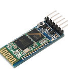
HC-05 Bluetooth Module
LED
HC-05 Bluetooth module has six pins:
-
KEY
-
VCC
-
GND
-
TX
-
RX
-
STATE
In this project I will simply show how to interface with the module using only four pin, VCC, GND, TX and RX.
VCC: is connected to a 3.3 volt but sometimes this doesn't matter if you give a 5 volt
GND: common ground
TX and RX are used for serial communication. This Bluetooth module comes with default baud-rates such as for example 9600, etc..and its default name HC-05.
Working:
You can download my apk file here to test ! if you do not have any other solution. In case you have the skill of programming android application then it is also good for you go head. The MIT University offers a free online building android software without writing a single line of code, try also to take a look from their website to update more. to work with my application you need to follow the step bellow:
Steps:
-
install the apk in your smart phone android
-
open the application
-
ON you Bluetooth
-
you will probably see on top scree a button "select your device" the select your HC-05
-
If you device is connected, then write something in the field textbox "put some text here" then click on write, this will send that string trough Bluetooth, but you need to leave the text Bluetooth selected from the combo box.
In case you are using the original code and correct connections of LEDs connected on PORTB then the result will be as follow if you respect to send the following strings to drive the LEDs ON and OFF:
-
11OK the first LED connected to the first pin of PORTB will be ON
-
22OK the first LED connected to the first pin of PORTB will be OFF
-
33OK the second LED connected to the second pin of PORTB will be ON
-
44OK the second LED connected to the second pin of PORTB will be OFF
-
55OK the third LED connected to the third pin of PORTB will be ON
-
66OK the third LED connected to the third pin of PORTB will be OFF
The characters in bold are the strings which has to be serially send to the micro-controller from the Bluetooth module, by default send these characters to see the result, the circuit diagram should be respected as shown in the right side, but the application which you use in your smart phone may be different but the string to be send must be item if you are using the original code or .Hex
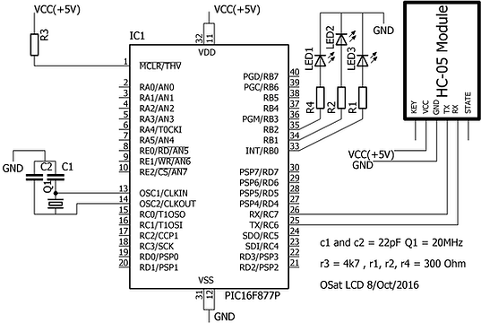
Circuit Diagram
The circuit diagram shown below is the very basic diagram required for interfacing HC-05 module with the 16F877A micro-controller. you need to respect the connections to get best result.
-
a resistor of value 4k7 ohm is connected in series with +5 volt and the reset pin (1st pin)
-
Q1 is the crystal oscillator in this case its frequency oscillation is 20 MHz.
-
supply: the circuit is connected with a voltage maximum equal 5 volt
-
R1,R2,R4 are limiting current resistors to protect the LEDs.
-
C1 & C2 are of 22pF.
#define baud_rate 9615
unsigned int i;
char OSat[3];
char red[] = {'1','2','3','4','5','6','\0'};
void main(void) {
UART1_Init(baud_rate);
Delay_ms(100);
TRISB.B0 = 0;
TRISB.B1 = 0;
TRISB.B2 = 0;
PORTB = 0X00;
for(;;) {
if(UART1_Data_Ready()){
UART1_Read_Text(OSat,"OK",7);
if(OSat[0] == red[0]){
PORTB.B0 = 1; // first LED is ON
}
if(OSat[0] == red[1]){
PORTB.B0 = 0; // first LED is OFF
}
if(OSat[0] == red[2]){
PORTB.B1 = 1; // second LED is ON
}
if(OSat[0] == red[3]){
PORTB.B1 = 0; // second LED is OFF
}
if(OSat[0] == red[4]){
PORTB.B2 = 1; // third LED is ON
}
if(OSat[0] == red[5]){
PORTB.B2 = 0; // third LED is OFF
}
} // end if(UART1_Data_Ready())
}// end for(;;) loop
} // en main function
Code and Comment
This code were written using mikroC compiler software, you can copy and compile it or modify it as well, this is used to show how to toggle LED using Bluetooth Module.
Download the full project here